Communication System
When we are exchanging information or sharing information with someone for example by speaking, writing or sending radio signals or in any form and the process of exchanging information or sharing is called as communication system.
How can we exchange information
We can exchange information by using phone, writing, radio signal, electronic messages, digital messages etc and if one person is speaking to other person this is said to in person communication and there are plenty of examples and number of ways one person can communicate from other.
Before entering deep into this topic we need to know about some basic terms related to this communication system. In general all we know that communication is a process of sharing or transferring or exchanging the information or message or data from one point to another point or from one end system to other end system. All we need to know that how this communication takes place.
Communication in Olden Days
In olden days communication is done through human (i.e., to transfer the message from one person to other person, third person is required for carrying the information from source person to destination person). This is known as physical mode of communication because here the data is physically carried by the person and non-verbal communication can also be referred as physical mode of communication. (In Physical mode of communication the speed is very limited), cost is high and also the reliability of the service is poor.
Communication System In Present Days
But the situation today in present days are completely different. we can communicate across the world to any place within seconds. The question is how this become possible? What development has made behind to reach this situation? We are going to discuss the history behind this modern communication system or electronic communication system. Lets get started with the baic block diagram of the modern communication system and also discuss each block in detail.
Block Diagram of Communication System
Figure 1 BLOCK DIAGRAM OF ELECTRONIC COMMUNICATION SYSTEM
Channel
First we start with the block channel. Remember communication is the process of imparting or exchanging the information from one place to other. Here the information that is produced by the source (i.e., transmitter side) has to travel several thousands of miles to reach the destination(i.e., receiver).Channel is the media through which this information is passed, this channel may be a wired example copper wire or wireless example air. In wired channel a dedicated cable is connected between the transmitter and the receiver where as in wireless it travels through the air. For short distances wired connection is preferable whereas, for larger distances wireless is used because it is difficult to have a dedicated wire or cable for long distances as it requires larger wire due to this the equipment becomes complex and for even far areas it is impossible to have a wired connection.
Noise and Distortion
Noise
Noise is an unwanted interference caused by some internal and external factors. Noise due to internal factors such as motion of electrons ,recombining of carriers is known as internal noise and noise caused by external factors such as ignition, lightening, electrical switching is known as external noise.
Distortion
Distortion is different from noise. distortion misleads the destination about the input signal by changing the characteristics of the input signal such as amplitude, frequency and phase. If this distortion parameters vary linearly known as linear distortion and nonlinearly known as non-linear distortion.
Input and Output Transducer
Transducer is a device used to convert one form of the information to other form. The information that is to be transmitted is first converted into electrical form. This conversion is done by the input transducer the need of this conversion is to deliver the information with high speed. Electrical signals moves with a speed equal to the speed of light. The output transducer performs the replica operation to that of input transducer it converts the electrical signal from channel to the corresponding form that user requires.
Transmitter
Transmitter modifies the input electrical signal to the form that is suitable for efficient transmission over the given channel. We have different types of transmitters for different types of channels. If the channel varies it is the responsibility of the transmitter to adjust itself with the varied channel for efficient communication. In general, this transmitter section contains several sub blocks such as modulator, A/D converter , encoder, amplifier.
Receiver
Receiver performs exactly the inverse operation of transmitter. It modifies the received electrical signal to the form that user understands. It also performs decoding, D/A conversion, demodulation.
Types of communication System
There are two types of communication system:
- Analog communication System.
- Digital Communication System
Analog communication
In Analog communication system the information from source to destination is communicated through Analog signals. Analog signals continuous in nature and varies with respect to time. Example speech, video, variation in temperature with respect to time.
Digital Communication
In digital communication system the information from source to destination is communicated through digital signals .Digital signals are discrete in nature and are represented by 0 or 1.Example mobile, Television etc.,
Terminology Used in communication System
The terms used in communication systems are
1. Signal
2. Transducer
3. Attenuation
4. Amplification
5. Bandwidth
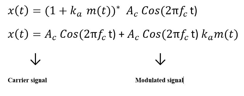
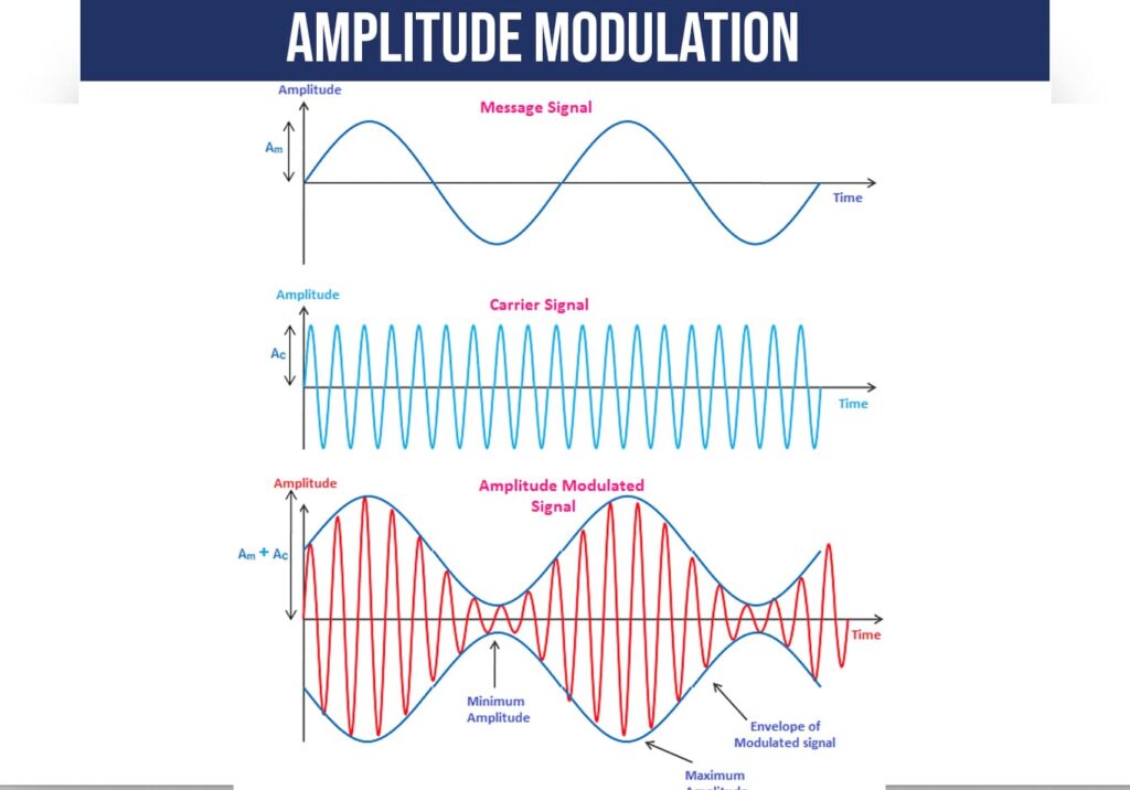
6. Modulation
7. Demodulation
8. Repeater
9. Noise
Frequently Asked Questions:
What is communication System:
communication is a process of sharing or transferring or exchanging the information or message or data from one point to another point or from one end system to other end system and the process of exchanging information or sharing is called as communication system.
Common terms related to communication system:
Source, Input transducer, based-band signal, transmitter, Channel, receiver, output transducer, Destination are the common terms used in communication system