Thursday, March 5, 2026
Home Blog Page 11

Transmission Media Types

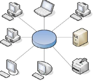
Types Of Transmission Media:

Transmission media is physical path which carry information from one device to another device.some of the examples of transmission media are Guided and Unguided media, transmission will always not in physical form but also it may invisible form. Transmission is categorised as follows:

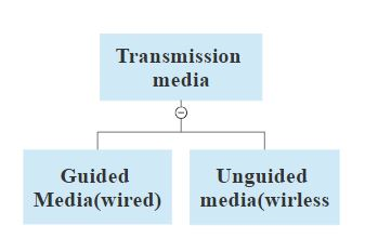
Fig: Types Of Transmission Media

Guided media:

Guided means there will be a physical connection between transmitter and receiver.some examples of guided media are twisted pair, coaxial-cable and fibre optics.

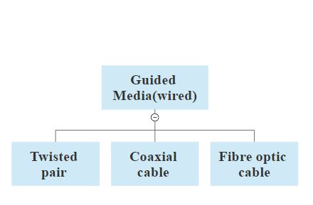
Fig : Guided media types

Twisted pair:

Twisted pair cables are mostly used for transmission of both voice and data signals, twisted pair wire are mainly categorised into two types. Shielded and unshielded twisted pair.

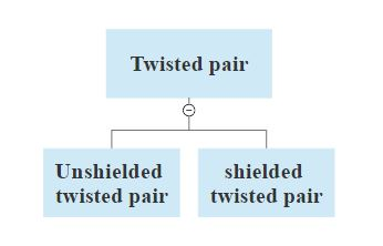
Fig : Twisted pair types

Unshielded twisted pair: (UTP)

UTP wires are mainly used in telephone systems which will carry both the voice and data signals.Unshielded twisted pair cable consist of two copper conductors, the wires will be kept parallel with this it will reduce noise. Noise will reduced  due to twist in the wire. The copper conductor is covered with insulators.some advantages of UTP are it is cheap,easy to install,flexible to use.

Shielded twisted pair: (STP)

The crosstalk which presented in UTP is eliminated in STP because STP wire has a metal shield covering that encase each pair of insulated conductor.

Applications of twisted pair:

  1. It is used for Data communication.
  2. It can handle a data speed of 100 Mbps.
  3. Useful for telephone networks.

Coaxial cable:

When compared with the both UTP and STP is more expensive and it is more complicated to install in a building because of more number of twists and turns. Coaxial cables are categorised according to radio government rating(RG). RG will provide some set of specifcations based on wire guage of inner conductor, thickness and type of the inner conductor.

categoryimpedanceUse
RG-5850 OhmsThin ethernet
RG-5975 OhmsCable TV
RG-1150 OhmsThick ethernet
Coaxial cable categories

Applications:

Used for both data and voice commnication.

Used in cable TV.

Fibre optics:

Fibre optical is combination of both glass and plastic which is useful for tranmission of information in the form of light eg: video,voice and data. protecting cover in fibre opic is made of fibre plastic or glass, core and cladding is made of plastic or glass. It works on the principle of “Total internal reflection”.when the light ray reflects back in the same medium is known as Total internal reflection.

Some advantages of fibre optic wires are;

  • It is more secure when compared with others.
  • Less expensive when compared with coaxial cable
  • It is small in size.
  • More flexible and strong.
  • Light in weight.
  • High information capacity.

Applications:

  • Used in Telecommunication.
  • Provide secure communication for the military.
  • Local and long-distance telephone communication.
  • Aircraft communication.
  • CCTV systems.
  • Ethernet and Gigabit ethernet.

Graph Search Strategy:

A graph search control strategy might explore many equivalent paths in producing a database containing only M’s.

Redundant Paths can lead to inefficiencies because the control strategy might attempt to explore all of them; worse it might do work that is wasted ultimately in exploring paths that do not terminate.

One way to avoid the exploration of these redundant paths is to recognize that the initial database can be decomposed or split into separate components that can be processed independently.

C B Z can be looked at as 3 distinct elements of C,B,Z so this is what we do here we break C B Z into  C, B and Z  then apply the rewriting rules that we have highlighted initially. So C can be written as D L or BM , B  is written as MM and Z is written  as  BMM.DL can be changed as D to D and  L,B M is BMM, MM is written as MM and BB MM is  again split as B M B .So, we had an initial C B  Z. We split it up as C,B and Z  applied the rewriting rules to get DL ,BM,MM, BMM. Then again split this into D and L,B M into B and M, MM into M and M and BMM as BMB. So then we start applying the rewriting rules and apply only to this B. And we get a string where all of these M’s are satisfied. Now, one thing to note here is very important property that we want to explore. If you look at here; at this point,  all of C, B and Z needs to be brought to termination. All of these parts are important. But at this point ,When I think of rewriting C as either DL and BM, I can rewrite only  in 1 one way, whereas again at the next lower level both of them needs to be looked at. All of 3  needs to be looked at here. But again here when I’m looking at , I look at only 1 alternate path but here there are no alternate path I have only 1 path So it became simpler here.

Properties of Commutative production system, Introduction to Decomposable production system

Properties of Commutative   production system

  1.  An irrevocable control regime can always be used in a commutative system because the application of a rule never needs to be taken back or undone.
  2. No need of a mechanism for applying alternative sequence of rules .The rule that is applicable  to an earlier database is applicable to the current one as well.
  3. In a commutative production system there may be a chance of having inappropriate rules. This inappropriate rule just delays but never prevents termination.

Decomposable production system

 In order to understand decomposable production system. Consider a system   which has initial database as (C,B,Z). The production rules are based on the following rules. C could be written as (D,L) ; C could be written as ( B,M) ; B could be written as (M,M) ; Z could be written as (B,B,M) i.e.,

R1 : C → ( D,L)

R2 : C → (B,M)

R3: B → (M,M)

R4: Z → (B,B,M)

 Here I’m looking for a termination condition where the database contains only M. If I start with  the complete C B Z I have 3 rewriting rules for C, B, Z so  my path would be 3 different distinct paths. I could write C or B or Z.

                                                            FIGURE  1

And each of them could take different paths. And what is important is to note that some path may lead to termination. But, some other path may not lead to termination . Instead of looking at C B Z as a complete single entity , the decomposable production system allows me to  look at C B Z as 3 different units of C B Z .This is because of the problem that  I get  when I look at it as 1 single unit as highlighted.

Open Systems Interconnection Model(OSI)

OSI (open systems interconnection)MODEL:

For providing communication between two devices international standard organisation(ISO) developed a model known as open systems interconnection(OSI). Osi model isn’t a protocol, it is a model for understanding and designing a specification that’s flexible and robust. It consist of 7 interconnected layers to passes information within the network. Seven layer in osi model are namely.

1.physical

2.data link

3. network

4.transport

5.session

6.presentation

7.application

Physical layer:

Physical layer is responsible for converting frames from datalink layer into bits at the receiving end, and bits from physical layer is given to datalink layer.some of the functions of physical layer is signal coding, representation of bits, physical topology,line configuration, data rate, transmission mode.

Datalink layer is responsible for converting packets from network layer into frames at the receiving end, and frames from datalink layer is given to network layer.it makes physical layer error free to the upper layers.some of the fuctions of datalink layer is framing, physical addressing, flow control, error control and access control.

Network layer:

 Network layer is responsible for converting data segements from session layer into packets at the receiving end, and packets from network layer is given to session layer. These layer defines routing for transmitting data from source to destination.some of the funtions of network layer are logical addressing, routing.

Transport layer:

Transport layer is responsible for end-to-end(source to destination) delivery of the entire message the layer converts data into smaller segements for sending and at the receiving end the segements are converted into original data.some of the funtions of transport layer are: service point addressing, segementation and reassembly, connection control, flow control, error control.

Session layer:

Responsibility of session layer is to establish, maintains and disconnects between communicating systems. It provides communication between two devices either in simple or half duplex mode.some of the functions of session layer are dialog control, syncronisation.

 Presentation layer:

Presentation layer cares with the syntax and semantics of the knowledge exchanged between two systems. It translates the application into network format and vice versa. some funtions of presentation layer are:Translation, encryption and decryption.

Application layer:

It provides end-users for the processing of data and supports services such as email, file transfer, shared data management, network software services, and other types of distributed information services, this layer acts as an interface between end-users and network. It allows mainly access to network resources.

Fig: OSI model

convolution of signals

0

Convolution for both signals and sequence:

Convolution is defined as mathematical way of combining two signals in order to form third the signal. It plays a significant role because it relates the input signal and impulse response of the system to the output of the system. Which is used to provide relationship of LTI system.

Some important properties of convolution are:

Let us consider two signals x1(t) and x2(t) for these the convolution is

x1(t)* x2(t) = ) )  = ) )

Commutative property:

The commutative property of convolution is

x1(t)*x2(t) = x2(t) *x1(t)

Distributive property:

The Distributive property of convolution is

x1(t)*[ x2(t)+ x3(t)]= [x1(t)* x2(t)]+[ x1(t)* x3(t)]

Associative property:

The Associative property of convolution is

x1(t)*[ x2(t)*x3(t)]= [x1(t)* x2(t)]* x3(t)

Convolution performs the following operations are:

  • Folding
  • Multiplication
  • Addition
  • Shifting

clc;

close all;

   clear all;

%program for convolution of two sequences

x=input(‘enter input sequence: ‘);

h=input(‘enter impulse response: ‘);

y=conv(x,h);

subplot(3,1,1);

stem(x);

xlabel(‘n’);

ylabel(‘x(n)’);

title(‘input sequence’)

subplot(3,1,2);

stem(h);

xlabel(‘n’);

ylabel(‘h(n)’);

title(‘impulse response sequence’)

subplot(3,1,3);

stem(y);

xlabel(‘n’);

ylabel(‘y(n)’);

title(‘linear convolution’)

disp(‘linear convolution y=’);

disp(y)

%program for signal convolution

t=0:0.1:10;

x1=sin(2*pi*t);

h1=cos(2*pi*t);

y1=conv(x1,h1);

figure;

subplot(3,1,1);

plot(x1);

xlabel(‘t’);

ylabel(‘x(t)’);

title(‘input signal’)

subplot(3,1,2);

plot(h1);

xlabel(‘t’);

ylabel(‘h(t)’);

title(‘impulse response’)

subplot(3,1,3);

plot(y1);

xlabel(‘n’);

ylabel(‘y(n)’);

title(‘linear convolution’);

NEED FOR DATA COMMUNICATION

REQUIREMENT FOR DATA COMMUNICATION:

Data communication and networking plays a significant role to perform some tasks.

Flow control of data:

In order to handle fast data flow which is sent from transmitter to receiver we require some data flow control mechanism while making agreement between two communicating devices.

Transmission system utilization:

To make tranmission channel usage more efficient while sharing information between two communcating devices we require transmission system utilisation.

Signal Generation:

Communicating devices should capable of generating signal and receiving of signals from transmitter.

Addressing:

If we want to share information between more than two devices source needs to provide its correct identity,in order to send the information to correct destination with the help of addressing.

Errror detection and correction:

While communicating between two devices the transmitted signal gets distored because of some intermediate devices. This errors in the transmitted signal is corrected at the receiver by using some error detection and correction codes.

Error detection methods: Parity checking, LRC, VRC, CRC etc.,

Error correction methods: Hamming codes, ARQ etc.,

Routing:

Router are used to send data to the destination.

PROTOCAL AND ITS TERIMINOLOGY:

Protocal:

Protocal may be defined how the communication will take place, what is communication and when communication should done. Some of key elements of protocal are:

syntax:

The word syntax refers to format or way of representing the data and meaning the order in which they are presented. Let us consider a example of simple protocal which defined first 8 bits for address of the sender, last 8 bits for receiver adress and rest of the bits for message itself.

semantics:

The term semantics is defined as meaning of section of bits, for example the identification of final destination of the message.

timing:

Timing terminology is important to determine when the data should be sent and how fast it should be sent.

EVEN AND ODD PARTS OF SIGNALS AND SEQUENCE

0

EVEN AND ODD PARTS OF SIGNALS AND SEQUENCE:

One of the most important characteristic of signal is symmetric which may be useful for signal analysis. When signal is symmetric around vertical axis it said to be even signal, when a signal is symmetric about origin is called odd signal.

Even signal:

When a signal is distinguished as even signal when it satisfies the below condition, for a continuous time signal x(t).

x(t)=x(-t) for all t

When a signal is distinguished as even signal when it satisfies the below condition, for a Discrete time signal x(n).

x(n)=x(-n) for all n

Cosine wave is an example of even signal.

clc;

close all;

clear all;

t=0:.001:4*pi;

x=sin(t)+cos(t); % x(t)=sin(t)+cos(t)

subplot(2,2,1)

plot(t,x)

xlabel(‘t’);

ylabel(‘amplitude’)

title(‘input signal’)

y=sin(-t)+cos(-t); % y(t)=x(-t)

subplot(2,2,2)

plot(t,y)

xlabel(‘t’);

ylabel(‘amplitude’)

title(‘input signal with t= -t’)

even=(x+y)/2;

subplot(2,2,3)

plot(t,even)

xlabel(‘t’);

ylabel(‘amplitude’)

title(‘even part of the signal’)

Odd signal:

When a signal is distinguished as odd signal when it satisfies the below condition, for a continuous time signal x(t).

x(-t)=-x(t) for all t

When a signal is distinguished as odd signal when it satisfies the below condition, for a Discrete time signal x(n).

x(-n)=-x(n) for all n

Sine wave is an example of odd signal.

clc;

close all;

clear all;

t=0:.001:4*pi;

x=sin(t)+cos(t); % x(t)=sint(t)+cos(t)

subplot(2,2,1)

plot(t,x)

xlabel(‘t’);

ylabel(‘amplitude’)

title(‘input signal’)

y=sin(-t)+cos(-t);

subplot(2,2,2)

plot(t,y)

xlabel(‘t’);

ylabel(‘amplitude’)

title(‘input signal with t= -t’)

odd=(x-y)/2;

subplot(2,2,3)

plot(t,odd)

xlabel(‘t’);

ylabel(‘amplitude’);

title(‘odd part of the signal’);

Even And Odd Parts Of Sequence:

clc;

close all;

clear all;

% Even and odd parts of a sequence

x1=[0,2,-3,5,-2,-1,6];

n=-3:3;

y1= fliplr(x1);%y1(n)=x1(-n)

figure;

subplot(2,2,1);

stem(n,x1);

xlabel(‘n’);

ylabel(‘amplitude’);

title(‘input sequence’);

subplot(2,2,2);

stem(n,y1);

xlabel(‘n’);

ylabel(‘amplitude’);

title(‘input sequence with n= -n’);

even1=.5*(x1+y1);

odd1=.5*(x1-y1);

% plotting even and odd parts of the sequence

subplot(2,2,3);

stem(n,even1);

xlabel(‘n’);

ylabel(‘amplitude’);

title(‘even part of sequence’);

subplot(2,2,4);

stem(n,odd1);

xlabel(‘n’);

ylabel(‘amplitude’);

title(‘odd part of sequence’);

Physical Topology

Topology:

The phrase topology is determined as physical the way network is laid; where two or more links form a topology. The reliability and efficiency of a network is depends on its structure. There are four fundamental topologies are ring, mesh, bus and star.

 Ring topology:

In this ring topology each node as a dedicated point to point link between each node. While a signal is passed from node to another node until it reaches its destination in the form of ring. In this ring topology each node act as repeater because each node in a ring receives the signal and regenerates the signal and send it to another node. The below figure shows a ring topology.

Fig: Ring topology

Some advantages of ring topology are:

  • It is easy to install and reconfigure,
  • Fault identification is easy.
  • It can travel long distance.

Mesh topology:

Mesh topology provides a dedicated point to point link to every node, the word dedicated is defined as which carrier traffic between two nodes.  In this mesh topology each node is connected to other node when link fails it does not incapacitate the entire system. Some of advantages of mesh topology are:

It is more robust.

It provide more security and privacy.

With mesh topology fault identification become easy.

Fig Mesh topology

Star topology:

Star topology is determined as each node provides a dedicated point to point link which is done through a central controller or known as hub. In this each node is not connected with each other directly. In star topology the central hub act as exchanger. When a node want to send a information to another node it first send information to the controller and then controller sends information to the other device. Some advantages of star topology are:

It is less expensive when compared with mesh topology.

It is easy to install and reconfigure.

If one link may fail it does effect other links.

Fault identification is easy.

Fig: Star topology

Bus topology:

Bus topology is differ from above three, because it  has multipoint configuration. In these nodes are connected to the bus cable by droplines and tap. A drop line is a connection between the nodes and main cable.A tap is a connector used to contact with the metallic core of the main cable and droplines. Some advantages of bus topology are:

Insatallation is easy.

It requires less amount of cables for connection of the computer, and les expensive.

Fig: Bus topology

BASIC OPERATIONS ON SIGNALS

0

BASIC OPERATIONS ON SIGNALS:

When we perform an operation signal it may undergoes several manipulation which may include amplitude of the signal or independent variable. Some basic operation are performed on signals. They are:

Time-shifting:

Time shifting of a signal x(n) may be defined as delay or advance of a signal in time, which is represented with the function.

y(n)=x(n+k)

When k is positive, then y(n) is shifted to right then the signal is delayed, when y(n) is shifted to left then the signal is advanced.

clc;

close all;

clear all;

t=0:.01:1;

x1=sin(2*pi*4*t);

%shifting of a signal 1

figure;

subplot(2,2,1);

plot(t,x1);

xlabel(‘time t’);

ylabel(‘amplitude’);

title(‘input signal’);

subplot(2,2,2);

plot(t+2,x1);

xlabel(‘t+2’);

ylabel(‘amplitude’);

title(‘right shifted signal’);

subplot(2,2,3);

plot(t-2,x1);

xlabel(‘t-2’);

ylabel(‘amplitude’);

title(‘left shifted signal’);

Time reversal:

Time reversal of a signal x(t) is defined as folding of a signal at t=0,it is very useful in convolution.

Y(t)=y(-t)

clc;

close all;

clear all;

t=0:.01:1;

x1=sin(2*pi*4*t);

h=length(x1);

nx=0:h-1;

subplot(2,2,1);

plot(nx,x1);

xlabel(‘nx’);

ylabel(‘amplitude’);

title(‘input signal’)

y=fliplr(x1);

nf=-fliplr(nx);

subplot(2,2,2);

plot(nf,y);

xlabel(‘nf’);

ylabel(‘amplitude’);

title(‘folded signal’);

Addition:

Addition of signal may be defined as adding of two continuous signals x1(t) and x2(t) at every time instant.

c(t) = x (t) + y (t)

clc;

close all;

clear all;

t=0:.01:1;

x1=sin(2*pi*4*t);

x2=sin(2*pi*8*t);

subplot(2,2,1);

plot(t,x1);

xlabel(‘time’);

ylabel(‘amplitude’);

title(‘input signal 1’);

subplot(2,2,2);

plot(t,x2);

xlabel(‘time’);

ylabel(‘amplitude’);

title(‘input signal 2’);

y1=x1+x2;

subplot(2,2,3);

plot(t,y1);

xlabel(‘time’);

ylabel(‘amplitude’);

title(‘addition of two signals’);

Multiplication:

Multiplcation of signal may be defined as multiplying of two continuous signals x1(t) and x2(t) at every time instant.

C(t)=x(t) y(t)

clc;

close all;

clear all;

t=0:.01:1;

x1=sin(2*pi*4*t);

x2=sin(2*pi*8*t);

subplot(2,2,1);

plot(t,x1);

xlabel(‘time’);

ylabel(‘amplitude’);

title(‘input signal 1’);

subplot(2,2,2);

plot(t,x2);

xlabel(‘time’);

ylabel(‘amplitude’);

title(‘input signal 2’);

y2=x1.*x2;

subplot(2,2,3);

plot(t,y2);

xlabel(‘time’);

ylabel(‘amplitude’);

title(‘multiplication of two signals’);

Scaling:

Scaling is defined as time expansion are compression of a given signal. Mathematically is represented as

Y(t)=x(at)

clc;

close all;

clear all;

t=0:.01:1;

x1=sin(2*pi*4*t);

A=2;

y=A*x1;

figure;

subplot(2,2,1);

plot(t,x1);

xlabel(‘time’);

ylabel(‘amplitude’);

title(‘input signal’)

subplot(2,2,2);

plot(t,y);

xlabel(‘time’);

ylabel(‘amplitude’);

title(‘amplified input signal’);

DATA FLOW

DATA FLOW:

Data communication between two devices can be simplex, half-duplex and full-duplex

Simplex:

In simplex mode the data communication will take place in one direction or unidirectional, only one device can transmit and other device will only receive the data. Some of the example of simplex mode is keyboard and monitor, in these the keyboard will transmit and monitor will accept it.

Half-duplex:

Where in half-duplex mode one station can transmit and other receive it and vice versa. In these mode both devices can transmit and receive but not at the same time. Walkie-talkie is an example of half duple mode.

Full duplex:

In a full-duplex mode, both the station can transmit and receive at the same time. It looks like two- way traffic road which allows the traffic in both the directions. One of the most common examples in full-duplex is the telephone line.

Network:

Network may be a set of nodes connected by communication links. While a device may be a computer, printer or other devices which has the capability of sending and receiving data generated by other devices on the network.

Network must meet some important criteria which may include performance, reliability and security.

Performance:

Performance may be defined as measuring of transmit time and response time. Transmit time is defined as amount of time required for a message to travel from one device to another device. Response time will be defined as the elapsed time between an inquiry and a response.

Reliability:  

Accurately delivery of data is defined in terms of reliability which is measured from the frequency failures.

Security:

Security is defined as protecting data from unauthorized access and from damage. Security can be provided to a network by using some rules and procedures.

Types of connection:

Network is defined as the combination of two or more devices connected via a physical path. A physical path is a link between two devices which transfer data from one device to another device. There are two types of connections. They are;

Point-to-point:

Point-to-point connection provides dedicated path between two devices, in these the entire capacity is reserved only between those two devices.

Multipoint:

Multipoint connection is defined as more than one device share a specific path, in this the entire path is shared temporarily are permanently between those devices.